Obviously we would like a speaker system to cover the broadest possible frequency range, have minimal response deviations, sound clean at any reasonable listening level and not be a slave to room placement. But how do we get there from here?
We can start by examining some basic principles of loudspeaker design.
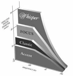
- A loudspeaker’s radiating area must increase in relation to the size of the wavelength reproduced to have uniform power distribution linear output
- Efficiency and dynamic range will increase as loud speaker piston area and motor size is increased.
- For a given sound pressure level, distortion will decrease as piston area and motor size is increased.
- Transient response characteristics usually improve as piston area and motor size is increased. (For you skeptics who still believe that an 8″ woofer is “quicker” than a 12″ woofer, remember this is a volume velocity issue. I bet you can empty a swimming pool faster with a bucket than a teaspoon!)
- Low frequency efficiency improves as enclosure cubic volume is increased. This translates to greater extension for a given amount of amplifier power.
- A properly tuned reflex enclosure will typically provide 6 dB more output than a sealed enclosure with a corresponding decrease in distortion due to lower cone displacement.
- Cascading a high pass filter with the proper Q characteristic will further enhance the low frequency output and extension of a reflex enclosure.
Does all this mean that a larger ported multi-way loudspeaker should play cleaner and deeper with better dynamics and more stable imagery? Absolutely. Still not convinced? Hold on to your seats for the next attraction. This table lists the lowest frequencies that may be reproduced in a LINEAR fashion by various high quality bass drivers at a given sound pressure when mounted in a sealed enclosure As a manufacturer of some very fine compact loudspeakers. I must admit it takes some courage to publish these data.)
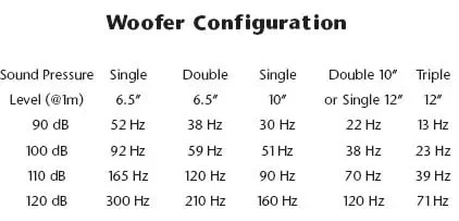
If you find this data shocking, remember that for each octave of bass extension we attempt to achieve, a given loudspeaker would have to increase its air displacement capability by a factor of four to prevent a rise in distortion. What does this mean in the real world? Take for example the B&W Nautilus 802 which measured in at 66% total harmonic distortion when presented with a 100 watt input of low E (41.2 Hz). Or consider the pricier Thiel CS-5 which measured in at 21.6% distortion at 100 dB of level when also presented with a low E (these data from the pages of AUDIO). The same magazine tested our dual 12Ó woofer configuration which measured an exceptionally low 3% distortion. Clearly we see that frequency response specifications, without reference to loudness or distortion levels do not tell the complete story.
Harnessing and Controlling Resonances
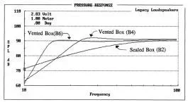
One way to extend the useful low frequency range of a loudspeaker is through enclosure venting. An optimal fourth-order Butterworth design will provide a significant increase in output over a sealed box design as shown in the pressure response plot below.

This additional energy is obtained by inversion of the backwave, which occurs at enclosure resonance. With the help of an electrical high pass filter, a more sophisticated sixth-order alignment can be obtained, providing greater extension and control. The sharply attenuated sixth-order configuration also rejects frequencies that are harmful to the loudspeaker itself.
As a side benefit, the reflex design greatly reduces cone excursion, which in turn minimizes distortion in the octave centered about resonance. The sixth-order alignment further reduces unwanted displacement in the first octave as shown below. Note that the cone displacement is nearly zero at system resonance while the half-power frequency is extended downward by a full octave. How’s that for extension and control?
So far we’ve discussed how resonance can work to our advantage by actually lowering distortion, increasing dynamic range and extending low frequency capabilities. Now let’s look at a way that resonance can actually hinder a loudspeaker’s performance.
The impedance curve below belongs to one of our metal dome tweeters. The curve is quite well behaved with the exception of a nasty rise centered at 780 Hz. This impedance bump is indicative of a resonance, natural to the driver’s construction and typical of a well designed 1″ dome unit.
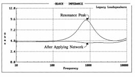
This resonance, if left untreated, will decrease power handling, increase distortion through diaphragm “breakup”, and cause instability in the crossover network. It can cause vocals to take on a characteristic “honk” that is quite annoying.
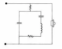
The electrical network shown in Figure 5 readily controls this resonance. This circuit is placed in parallel with the tweeter itself, so that transient response is in no way compromised. That’s the good news. Now for the bad news: I have personally examined the internal workings of more than 50 models of high-end loudspeakers and have found only two other manufacturers that bothered to install such networks. At least the other guys spared no expense in their advertising campaigns.
Since we’ve already harnessed two kinds of resonance, how about a third? Room resonance. No quite so simple this time.
For many years, designers have regarded the listening room as the great unknown. A set of variables involving room geometry, absorption coefficients, and decay patterns. Designers have presented almost as many knee-jerk solutions to room problems as there are rooms. Dipolar, bipolar, cylindrical, omnidirectional, and highly directional radiators to name a few. Electrostatic, moving coil dynamic, ionic, planar dynamic, thermodynamic, and even plasmic transducers. Designs that push air, reflect air, heat air, and squeeze air. Ah, the “art” of speaker design.
While there have been a number of acoustic studies over the past 50 years that have dealt specifically with the loudspeaker/listening room interface, rarely does such work have a significant influence on speaker design. Sometimes I think that speaker designers are just too flamboyant to pay heed to another designer, let alone learn from his mistakes. About two decades ago Amar Bose convinced himself that the stereo effect required 1/9 directivity and 8/9 reflectivity (I don’t think I’ll ever figure that one out). Peter Walker of Quad assured the world that a dipolar traveling wave originating as a point source was the key (Peter’s sonic result is pretty tough to argue with). Roy Allison showed us how to incorporate low frequency reflections as part of our designs (Thank you, Roy).
But before I climb upon my soapbox and start preaching the gospel according to Dudleston, might I pose the following questions? Don’t rooms usually have a floor? Isn’t the floor often the nearest room boundary to the listener? Don’t we usually face in the direction of the loudspeakers when we listen to them? Don’t most of us sit about 10 feet from our loudspeakers (+/- 2-ft.)?
I once spoke with a 60 year old carpet layer who said that the average living room is about 14′ x 20′ with two doorways, one set of curtains, and an 8′ ceiling. A friend of mine who is a painter suggests that over 90% of living rooms have carpeted floors or at least one large area rug. It seems that the speaker designer has plenty of information before him. Using such a room model would certainly be more ideal than relying exclusively on the laboratory abyss, more commonly known as the anechoic chamber.
The speakers that I design provide controlled directivity patterns. My strategy is as follows: include low frequency room gain as part of the speaker system, keep midrange reflections to an absolute minimum, if the midrange reflections can’t be minimized then add enough diffuse high frequency output to balance the mix (via a switchable rear-firing treble unit) without increasing on-axis brightness.
Whisper behaves as an acoustic gun, effectively widening the “sweet spot” and minimizing room interactions. Our FOCUS speaker provides deep nulls at the floor and ceiling to maintain clarity in any size room. The Signature III and Classic provide unusually broad horizontal coverage affording a sense of depth, even in cramped quarters by employing a rear firing ambiance tweeter.
In summary, physics dictates that a loudspeaker’s effective radiating diameter should increase with wavelength of sound to provide low distortion, broad dynamic range and uniform power distribution. I feel that a plot, such as the one above, is a very useful tool in approximating the potential performance level of a loudspeaker system.